- 您现在的位置:买卖IC网 > Sheet目录629 > PAXLR000 (Red Lion Controls)METER RATE INDICATION 6-DIGIT
�� �
�
�2.0� S� ETTING�
�THE�
�S� WITCHES�
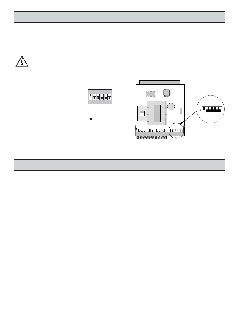
�The� meter� has� switches� that� must� be� checked� and/or� changed� prior� to�
�applying� power.� To� access� the� power� switch,� remove� the� meter� base� from� the�
�case� by� firmly� squeezing� and� pulling� back� on� the� side� rear� finger� tabs.� This�
�should� lower� the� latch� below� the� case� slot� (which� is� located� just� in� front� of� the�
�finger� tabs).� It� is� recommended� to� release� the� latch� on� one� side,� then� start� the�
�other� side� latch.�
�Power� Selection� Switch�
�Caution:� Insure� the� AC� power� selection� switch� is� set� for� the�
�proper� voltage� before� powering-up� the� meter.� The� meter� is� shipped�
�from� the� factory� in� the� 230� VAC� position.�
�Set-Up� DIP� Switches�
�A� DIP� switch� is� located� at� the� rear� of� the� meter,�
�and� is� fully� accessible� when� the� unit� is� in� the� case.�
�It� is� used� for� the� selection� of� the� input� parameters�
�SWITCH� 3�
�HI� Frequency� :� Removes� damping� capacitor� and� allows� max.� frequency.�
�LO� Frequency� :� Limits� input� frequency� to� 50� Hz� and� input� pulse� widths�
�to� 10� msec.�
�SWITCH� 4�
�LOGIC� :� Input� trigger� levels� V� IL� =� 1.5� V� max.;� V� IH� =� 3.75� V� max.�
�MAG� :� 200� mV� peak� input� (must� have� SRC� on).�
�SWITCH� 5�
�Enable� Programming� :� Enables� programming� through� the� front� panel� buttons.�
�Disables� Programming� :� Disables� the� front� panel� buttons� from� any�
�programming� changes.�
�SWITCH� 6�
�Not� Active� for� the� Rate� Meter�
�FRONT� DISPLAY�
�and� program� disable.�
�ON�
�POWER�
�SELECTION�
�1� 2� 3� 4� 5� 6�
�SWITCH�
�ON�
�1�
�2�
�3�
�4�
�5�
�6�
�230�
�Factory� Setting�
�SWITCH� 1�
�SNK.� :� Adds� internal� 7.8� K� ?� pull-up� resistor� to� +� 12� VDC,� I� MAX� =� 1.9� mA.�
�115�
�SWITCH� 2�
�SRC.� :� Adds� internal� 3.9� K� ?� pull-down� resistor,� 8� mA� max.� @� 30� VDC� max.�
�REAR� TERMINALS�
�INPUT� SET-UP�
�DIP� SWITCHES�
�3.0� W� IRING�
�THE�
�M� ETER�
�WIRING� OVERVIEW�
�Electrical� connections� are� made� via� screw-clamp� terminals� located� on� the�
�back� of� the� meter.� All� conductors� should� conform� to� the� meter� ’s� voltage� and�
�current� ratings.� All� cabling� should� conform� to� appropriate� standards� of� good�
�installation,� local� codes� and� regulations.� It� is� recommended� that� the� power�
�supplied� to� the� meter� (DC� or� AC)� be� protected� by� a� fuse� or� circuit� breaker.�
�When� wiring� the� meter,� compare� the� numbers� embossed� on� the� back� of� the�
�meter� case� against� those� shown� in� wiring� drawings� for� proper� wire� position.� Strip�
�the� wire,� leaving� approximately� 0.3"� (7.5� mm)� bare� lead� exposed� (stranded� wires�
�should� be� tinned� with� solder.)� Insert� the� lead� under� the� correct� screw-clamp�
�terminal� and� tighten� until� the� wire� is� secure.� (Pull� wire� to� verify� tightness.)�
�EMC� INSTALLATION� GUIDELINES�
�Although� this� meter� is� designed� with� a� high� degree� of� immunity� to� Electro-�
�Magnetic� Interference� (EMI),� proper� installation� and� wiring� methods� must� be�
�followed� to� ensure� compatibility� in� each� application.� The� type� of� the� electrical�
�noise,� source� or� coupling� method� into� the� meter� may� be� different� for� various�
�installations.� The� meter� becomes� more� immune� to� EMI� with� fewer� I/O�
�connections.� Cable� length,� routing,� and� shield� termination� are� very� important�
�and� can� mean� the� difference� between� a� successful� or� troublesome� installation.�
�Listed� below� are� some� EMC� guidelines� for� successful� installation� in� an�
�industrial� environment.�
�1.� The� meter� should� be� mounted� in� a� metal� enclosure,� which� is� properly�
�connected� to� protective� earth.�
�2.� Use� shielded� (screened)� cables� for� all� Signal� and� Control� inputs.� The� shield�
�(screen)� pigtail� connection� should� be� made� as� short� as� possible.� The�
�connection� point� for� the� shield� depends� somewhat� upon� the� application.�
�Listed� below� are� the� recommended� methods� of� connecting� the� shield,� in� order�
�of� their� effectiveness.�
�a.� Connect� the� shield� only� at� the� panel� where� the� unit� is� mounted� to� earth�
�ground� (protective� earth).�
�b.� Connect� the� shield� to� earth� ground� at� both� ends� of� the� cable,� usually� when�
�the� noise� source� frequency� is� above� 1� MHz.�
�4�
�c.� Connect� the� shield� to� common� of� the� meter� and� leave� the� other� end� of� the�
�shield� unconnected� and� insulated� from� earth� ground.�
�3.� Never� run� Signal� or� Control� cables� in� the� same� conduit� or� raceway� with� AC�
�power� lines,� conductors� feeding� motors,� solenoids,� SCR� controls,� and�
�heaters,� etc.� The� cables� should� be� ran� in� metal� conduit� that� is� properly�
�grounded.� This� is� especially� useful� in� applications� where� cable� runs� are� long�
�and� portable� two-way� radios� are� used� in� close� proximity� or� if� the� installation�
�is� near� a� commercial� radio� transmitter.�
�4.� Signal� or� Control� cables� within� an� enclosure� should� be� routed� as� far� as� possible�
�from� contactors,� control� relays,� transformers,� and� other� noisy� components.�
�5.� In� extremely� high� EMI� environments,� the� use� of� external� EMI� suppression�
�devices,� such� as� ferrite� suppression� cores,� is� effective.� Install� them� on� Signal�
�and� Control� cables� as� close� to� the� unit� as� possible.� Loop� the� cable� through� the�
�core� several� times� or� use� multiple� cores� on� each� cable� for� additional� protection.�
�Install� line� filters� on� the� power� input� cable� to� the� unit� to� suppress� power� line�
�interference.� Install� them� near� the� power� entry� point� of� the� enclosure.� The�
�following� EMI� suppression� devices� (or� equivalent)� are� recommended:�
�Ferrite� Suppression� Cores� for� signal� and� control� cables:�
�Fair-Rite� #� 0443167251� (RLC#� FCOR0000)�
�TDK� #� ZCAT3035-1330A�
�Steward� #� 28B2029-0A0�
�Line� Filters� for� input� power� cables:�
�Schaffner� #� FN610-1/07� (RLC#� LFIL0000)�
�Schaffner� #� FN670-1.8/07�
�Corcom� #� 1� VR3�
�Note:� Reference� manufacturer� ’s� instructions� when� installing� a� line� filter.�
�6.� Long� cable� runs� are� more� susceptible� to� EMI� pickup� than� short� cable� runs.�
�Therefore,� keep� cable� runs� as� short� as� possible.�
�7.� Switching� of� inductive� loads� produces� high� EMI.� Use� of� snubbers� across�
�inductive� loads� suppresses� EMI.�
�Snubber:� RLC#� SNUB0000.�
�发布紧急采购,3分钟左右您将得到回复。
相关PDF资料
PB52233SLK
PROJ BOARD COLDFIRE M52
PD412411
DIODE MOD ISO DUAL 2400V 1100A
PF24-30
TRANSFORMER LO PRO 15VAC 1.6A
PFT12-28
TRANSFORMER 16VCT 28VCT 12VA
PFT12-35
TRANSFORMER 16VCT 35VCT 12VA
PFT24-28
TRANSFORMER 16VCT 28VCT 24VA
PFT24-35
TRANSFORMER 16VCT 35VCT 24VA
PFT6-32
TRANSFORMER 17.5VCT 31.5VCT 6VA
相关代理商/技术参数
PAXLRT00
功能描述:METER RTD TEMP 4-DIGIT RoHS:是 类别:工业控制,仪表 >> 仪表 - 面板,数字 系列:PAX®LITE 标准包装:12 系列:* 其它名称:Q7072030
PAXLSG00
功能描述:METER STRAIN GAGE 3 1/2-DIGIT RoHS:否 类别:工业控制,仪表 >> 仪表 - 面板,数字 系列:PAX®LITE 标准包装:12 系列:* 其它名称:Q7072030
PAXLT000
制造商:Red Lion Controls 功能描述:METER, TC/RTD TEMP WITH DUAL RELAY 制造商:Red Lion Controls 功能描述:TC/RTD TEMP WITH DUAL RELAY
PAXLT0U0
制造商:Red Lion Controls 功能描述:METER, UL LISTED TC/RTD TEMP W/ D RELAY 制造商:Red Lion Controls 功能描述:UL LISTED TC/RTD TEMP WITH DUAL
PAXLTC00
功能描述:METER THERMOCOUPLE 4-DIGIT RoHS:否 类别:工业控制,仪表 >> 仪表 - 面板,数字 系列:PAX®LITE 标准包装:12 系列:* 其它名称:Q7072030
PAXLVA00
功能描述:VOLTMETER AC 3 1/2-DIGIT RoHS:是 类别:工业控制,仪表 >> 仪表 - 面板,数字 系列:PAX®LITE 标准包装:12 系列:* 其它名称:Q7072030
PAXLVD00
功能描述:VOLTMETER DC 3 1/2-DIGIT RoHS:是 类别:工业控制,仪表 >> 仪表 - 面板,数字 系列:PAX®LITE 标准包装:12 系列:* 其它名称:Q7072030
PAXOEMS1
制造商:Red Lion Controls 功能描述:SOFTWARE AND USB CABLE RS232